|
The Peak Heating Region is tricky to fly, as one needs to balance thermal loading with drag. On the one hand, if
you slow down too quickly, you could overload your ship's thermal protection system. On the other, if you slow down
too slowly, you could slow roast your ship's structure and ablate the thermal protection system, with equally bad results.
This problem was addressed during Shuttle's paper studies way back in the 1970's, and for Delta Glider, it is addressed by
the "once-around" deorbit, which ensures plenty of range over which to dissipate. The entry this tutorial was modelled
on never activated the particle entry flames in Orbiter (the "Final Frontier" picture on the home page was a different entry.)
The "flameless" entry is only possible with the Delta Glider emptied of propellants and from bound orbits (i.e. not interplanetary
aerocaptures.)
The heating region is the product of dynamic pressure and speed, so maintaining a constant heating rate involves raising
dynamic pressure slowly enough that speed multiplied by dynamic pressure produces the same number as the entry progresses.
(about 30,000 kPa*m/s or W/m^2 for this entry.) A thermodynamicist might be able to tell me what sort of temperatures
I'm experiencing, but that ain't me so drat. If you just happen to be a thermodynamicist, my email is at the bottom
of the home page http://aftercolumbia.tripod.com.
The goal is to maintain a constant heating rate until the Orbiter is below 13,000 mph (19,000 fps)
[5,800 m/s] - this is the temperature control phase.
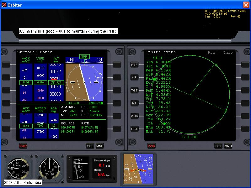
For this entry, and noted for later entries, is that I brought the drag up to 0.5 m/s2 too early, and had to use the
trim reserve L/D of 5.5 later during the entry to save my bacon.
Drag responds to the dynamic pressure "DNP" on the Surface MFD, and the generally fixed hypersonic aerodynamic parameters
of the ship being flown. Dynamic pressure responds to air density and airspeed squared. The airspeed
is what you are working so hard to dissipate, so you have much greater control of density through altitude control.
So, controlling drag means controlling altitude, which responds to sink rate ("VSPD"), which in turn responds to vertical
accelleration ("VACC").
Your instrument scan should therefore include ACC (drag), VACC (vertical accelleration), VSPD (sink rate), SPD (airspeed),
and either "Dst:" in the Map MFD, or you can download an addon Entry MFD from http://www.orbithangar.com which automatically calculates desired constant drag.
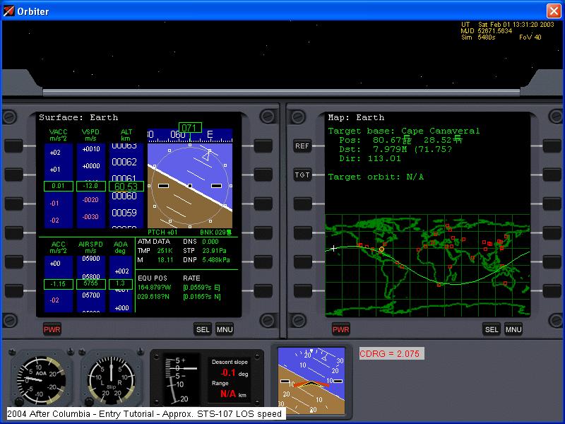
The time indicated in the above screenshot is 11 minutes and 4 seconds prior to, and in the same location (less quite
a bit of altitude) as the beginning of STS-107's deorbit burn. The landing wound up being 3 and a half minutes later
than STS-107's would have been, illustrating just how different the pussycat Delta Glider's entry is compared to the Shuttle.
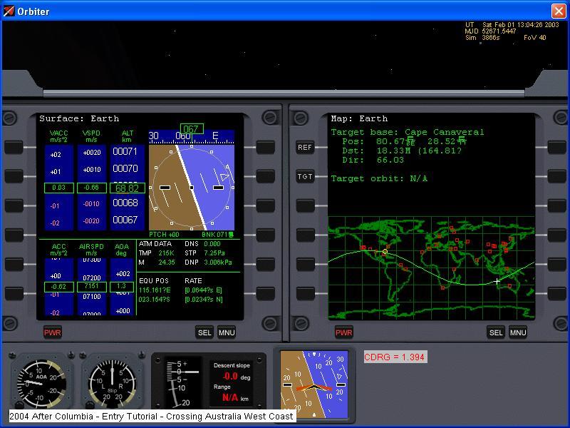
The new CDRG "instrument" was added to the panel in response to the crossing of the antipode, or other side of the planet,
from the landing site, still some 20,000km away. This is not an actual instrument in the panel, but a manual calculation
edited in to look like one, as it is in all subsequent screenshots. The formula to use is:
a = v^2/(2*d)
Where:
a = desired constant drag
v = ground relative speed (in Orbiter, airspeed and groundspeed are the same, as wind is not yet modelled.)
d = distance to base.
If in a calculator, the speed is entered in m/s and distance entered in km, the value will come out exactly 1000fold
above what it actually is...I move the dot in my head. The alternative, of course, is to use the aforementioned EntryMFD.
The above picture shows the actual drag at about half of the desired constant drag. This is actually far too much
for this phase of flight and should be at 0.5 or less. The reason is that induced drag from lift at full gravity is
about 3 m/s^2, which means that the constant drag value has to be that or more before I can increase the drag rate up to constant
drag.
If I had damage similar to STS-107, aerodynamic trim changes would be obvious at this point, and rather annoying if they
wouldn't be terrifying. At 80 psf dynamic pressure (converted from value shown), the wing would indeed need to be very
weak before it would fall off. There is not a whole lot of mechanical loading at this point. Overall, the
size of STS-107's hole would not have much effect on where Columbia lost control and broke up, but location
certainly would:
1. On RCC outboard of Panel 8/9 on a wing: The entry would last longer and to lower speeds as the entry plasma is cooler
(Panel 8/9 is the hottest spot on the whole Orbiter, except maybe the very tip of the nose) and also because damage within
the wing would progress slower than on STS-107.
2. On RCC inboard of Panel 8/9 on a wing: The entry would last longer and to lower speeds, again because the entry plasma
is cooler in this area. If inboard of panel 6 on the wing, the plasma has a direct shot through a spar window at the
tires, and loss of control would probably result from explosion of the wheels. Because the wheels are made of aluminum,
and the tires are steel belted radials, with uniform heating, the wheels would fail first. This is consistent with left
wing debris that has blasted bald tires, but no trace of the wheels. On STS-107, loss of control did not result from
the wheels exploding, but apparently, the wheels did explode between loss of control and ground impact.
3. On HRSI tile. This is where size matters, because the entry plasma is forced along the lower surface by the
leading edge. A hole the size of the one on STS-107 all the way down to bare aluminum would have little effect.
In fact, prior to STS-107, a Shuttle did experience this level of damage.
4. Gear door seal: This was thought to be the worst case scenario just prior to STS-107's entry attempt.
The results would have been very similar, but with a different pattern of sensor failures. The elevon hydraulic return
temperatures probably would not have been lost all the way to loss of signal, and the wheels exploding would probably be the
cause of loss of control.
5. The RCC nose cone: Very likely to have resulted in an earlier break up, possibly over California. The reason
is that a parade of pressure vessels, starting with those in the FRCS greets the plasma. If nothing else failed first,
entry of plasma into the cabin, and the resulting decompression, would have caused both loss of control and the death of the
crew (as none of them had their ACES pumpkin suits fully donned.)
6. Anywhere else: I might have missed a few spots, but essentially anywhere I haven't mentioned so far would have
no effect on the entry.
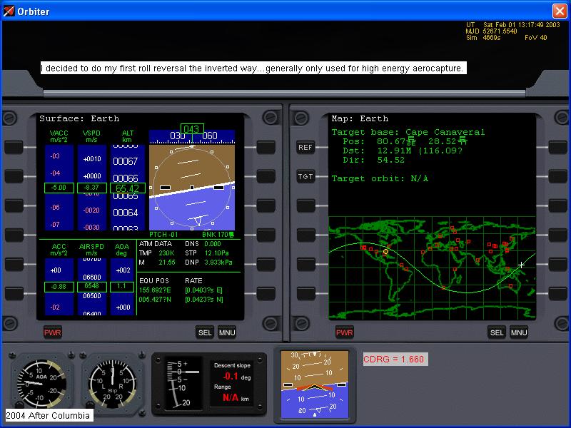
I chose to do my first roll reversal by going inverted. This tactic is _not_ recommended for new flyers!
Roll reversals early in entry are actually rather tricky. First, you need to increase your sink rate so that the
climb resulting from a roll reversal doesn't throw you out of the atmosphere back into space by accident, and also to buy
a few extra seconds on the other side of the roll reversal to fine trim the roll angle to bring the sink rate back to normal
(which is about 10-20m/s throughout the peak heating region. I would not recommend higher sink rates because drag can
build up too quickly, nor lower sink rates because lift can die out, leading to very irritating sink rate oscillations...essentially,
you are unable to maintain lift against rapidly building gravity, fall and once levelled off, have too much drag and need
to climb back up again.)
Roll angle is also used to control cross-range. Azimuth error is the angle between the plane
containin the Orbiter's position vector and the heading alignment circle tangency point, and the plane containing the Orbiter's
position vector and the Orbiter's velocity vector. When the azimuth error exceeds a predetermined number, the Orbiter's
roll angle is reversed.
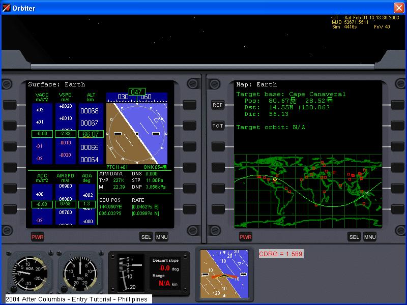
Don't panic! It's not as complicated as it sounds with that crazy vocabulary. Compare the last two images
Map MFDs. The first one shows the orbit plane wave considerably north of the Cape, while the second one shows the wave
quite a ways south. The wave between you and the target base is a great circle...or the shortest way to get there.
It will move depending on which way you are rolled and how much. Once it gets far enough away, do a roll reversal so
you don't wind up off course. I usually do about 7, while the Shuttle usually does 4.
As the entry continues, both drag and dynamic pressure increase. Here, we are at 114.5 psf, which is enough to
rip off a melted wing, especially as heating rates are not going down. If I were to break up at this point, I would
need a very tough capsule and endure about 15g on the way down. It is impractical to design a craft to survive a breakup
in this area. Delta Sprint takes the approach of using a layered thermal protection system and impact shielding to prevent
damage to the critical parts of the thermal protection system.
Breakup dynamics: During STS-107's last few minutes, the Columbia first lost the badly
weakened left wing. The aerodyamic forces (vary as dynamic pressure) had built up to the point where the roasted left
wing was no longer capable of sustaining itself. A depression formed in the bottom of the wing behind the panels in
front of the spar which forms the back of the wheel well (techspeak: in the area of Xo1040 to Xo1191 outboard of the left
main landing gear bay.) Just prior to loss of signal, the wing leading edge in this area began to stall as bending progressed,
producing a rapidly increasing roll and yaw moments. From 2 seconds before loss of signal until 8 seconds after, the
Shuttle was able to counter these forces by pushing every available control surface and thruster to its limit.
The seriously weakened left wing spars bent back and up as the vehicle lost control smashing into
the left OMS pod and severing the aileron hydraulic lines, causing the loss of all hydraulic pressure. The left wing
became Debris A, B, and C in the videos. The left wing debris, as plainly seen in the video, slowed down much faster
than the rest of Columbia. Left wing debris dominated the western debris area, characterized by tiles that
were baked off rather than broken off.
The tumbling Orbiter began breaking up into its major subassemblies about 30 seconds later as thermal
and aerodynamic loads combined to exceed her structural capabilities. The major subassemblies further subdivided, with
the forward and aft fuselage structures lasting the longest. As Columbia continued to break up, she produced
debris of varying ballistic coefficient. The lighter (lower coefficient) debris slowed down in the steadily thickening
air and fluttered to the ground in eastern Texas, while the heaviest (highest coefficient) debris were the powerheads and
combustion chambers of the three main engines. One of these crashed into a Louisiana golf course at an estimated impact
speed of Mach 3. These heavy parts carried enough energy that they were not able to dissipate it before hitting the
ground.
As ballistic debris travels through the atmosphere, drag causes it to slow down horizontally, while
gravity causes it to accellerate downward. Light debris will have enough drag to keep gravity from bringing it down
quickly, and won't travel as far. (Really light debris can be carried by the wind and theoretically travel even farther than
heavy debris.) Heavy debris slow down in the atmosphere, but still are accellerated by gravity. Even though this
debris travels horizontally the farthest, it is still coming straight down at impact because of gravity and lack of lift.
Managing drag and heat in the Delta Glider:
This entry profile is intended to provide an excess of downrange to allow the Delta Glider to more slowly dissipate its
enormous speed. Flying simulators destroy the mindboggling nature of these numbers. When you are riding the fireball
in the sim, spaceflight is something you can grab with your hands and understand.
When flying, do not be ashamed to pause to figure things out, to slow the sim down. Remember that the real vehicles
are flown by computers that can make a thousand decisions every second and dozens of engineers have worked it all out in advance
(in part by flying sims like this.) You can only do that by slowing the sim down and pausing. You don't have the hundreds
of collective years of education and experience that goes into an entry (incidently, neither does After Columbia.) Save
(Ctrl-S) often, and by all means take notes (screenshots, pencil and paper, flight recorder module, hypercam, tape recorder...whatever
is your preference.)
Drag Management Formulae :
Key:
a = drag (accelleration) in metres per second squared, m/(s^2) or ms^-2. To convert to fps/s, multiply by 3.28.
v = speed in meters per second, m/s. To convert to fps/s, multiply by 3.28. To convert to kph, multiply by
3.60. To convert to mph, multiply by 2.237. To convert to knots multiply by 1.943.
d = range (distance) to go in metres. Instruments usually give this in kilometres, so when entering in calculator,
either add three zeros or remember that your result will be exactly 1000 times too high (I use the latter method.)
This is actually the same formula rearranged different ways within the abilities of a high school graduate.
Finding drag: a = v ^ 2 / ( 2 * d ) [basic calculator: v * v / 2 / d]
Finding distance: d = v ^ 2 / ( 2 * a ) [Basic calculator: v * v / 2 / a]
(Note that the answer will be given in metres, a basic 8 digit calculator will crash if the distance result
exceeds 100,000,000 metres, or 100,000 kilometres. The most the instrument in the Map MFD will ever read is just a tad
over 20,000 kilometres, so if your distance result crashes your calculator, it is most likely an input error or you are entering
a drag number that would take you around the world at least twice if you could keep it that low. Initial entry is governed
by this level of drag, but it can't be kept low.
Finding speed: _/ ( 2 * a * d ) [Basic Calculator: 2 * a
* d = _/ ("_/ is the closest approximation to the square root symbol that can be done with standard web page characters.]
This formula needs to have the distance entered
in metres. If distance is entered in kilometres, it will be off by the awkward factor of _/1000 or 31.62, so remember
those last three zeros. Finding speed is nice if you are flying wings level and can't get your drag below a certain
value. When your drag exceeds the desired drag formula above, it is impossible to make the landing site when you are
in a condition where you can't reduce your drag any further. At this point, it is nice to be able to specify your actual
drag value and figure out how fast you _should_ be going at that distance to go for next time.
Right now (and this does need to be refined)
the recommended drag/distance schedule for Delta Glider is:
|
|
|
|
|
|
|
|
|
|
|
|
|
|
|
|
|
|
|
|
|
|
|
|
|
|
Approach and maintain desired ~3.50 m/s^2 or value from calculation or Entry MFD
|
* >20000km is more than halfway around the world. The Map MFD will always read less than 20015km.
When range is more than 20015km in the direction you are travelling, the value displayed is lower than 20015km and increasing.
|